#75 A soil profile consisting of three layers is shown in Figure
A soil profile consisting of three layers is shown in Figure - Civil Engineering
Chemistry Explain daily providing Q&A content “#75 A soil profile consisting of three layers is shown in Figure” this question is coming from Civil Engineering

Chemistry Explain team has covered all Topics related to inorganic, organic, physical chemistry, and others So, Prepare these Chemistry Questions and Answers with Explanation Pdf.
Questions
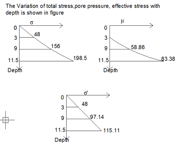
Through 9.3 A soil profile consisting of three layers is shown in Figure 9.25. Calculate the values of Ï, μ, and Ïâ at points A, B, C, and D for the following cases. In each case, plot the variations of Ï, μ, and Ï with depth. Characteristics of layers 1, 2, and 3 for each case are given below:


Answer
Srep 1Calculate the effective stress using the formula,
 â¦â¦ (1)
Here,
 is the total stress, and u is the pore water pressure.
Calculate the pore water pressure using the formula,
 â¦â¦ (2)
Here,
 is the unit weight of water, and H is the depth of the groundwater table.
Calculate the total stress using the formula,
 â¦â¦ (3)
Here, H is the height of the soil layer and
 is the unit weight of the soil.
Step 2
Consider point A.
As depth of soil layer and depth of ground water table at point A is zero, total stress, pore water pressure and effective stress at point A is zero.

Therefore, the pore water pressure at A is
 , total stress at A is
  , and effective stress at A is
  .
.Step 3
Consider point B.
Here, the depth of the soil layer is
 , and dry unit weight of sand layer is
  .
.Substitute 0 for
 ,
,  for
for  , and
, and  for
for  in equation (3), to calculate the total stress at B.
As the depth of ground water table at point B is zero, pore Water pressure at B is zero.

Substitute
 for
for  , and
, and  for
for  in equation (1), to calculate the effective stress at B.
Therefore, the pore water pressure at B is
 , total stress at B is
  , and effective stress at B is
  .
.Step 4
Consider point C.
Here, the depth of the soil layer is
 , and saturated unit weight of sand layer is
  .
.Substitute
 for
for  ,
,  for
for  , and
, and  for
for  in equation (3), to calculate the total stress at C.
Substitute
 for
for  , and
, and  for
for  in equation (2), to calculate pore water at C.
Step 5
Substitute
 for
for  , and
, and  for
for  in equation (1), to calculate the effective stress at C.
Therefore, the pore water pressure at C is
 , total stress at C is
  , and effective stress at C is
  .
.Step 6
Consider point D.
Here, the depth of the soil layer is
 , and saturated unit weight of sand layer is
  .
.Substitute
 for
for  ,
,  for
for  , and
, and  for
for  in equation (3), to calculate the total stress at D.
Step 7
Substitute
 for
for  ,
,  for
for  , and
, and  for
for  in equation (2), to calculate pore water at D.
Substitute
 for
for  , and
, and  for
for  in equation (1), to calculate the effective stress at C.
Therefore, the pore water pressure at D is
 , total stress at D is
  , and effective stress at D is
  .
.Step 8
Tabulate the obtained values of
 ,
,  , and
, and  for different layers.
| Points |  |
 |
 |
 |
| A | 0 | 0 | 0 | 0 |
| B | 3 | 48 | 0 | 48 |
| C | 9 | 156 | 58.86 | 97.14 |
| D | 11.5 | 198.5 | 83.38 | 115.12 |
Step 9
Plot the variation of total stress with depth for points A, B, C, and D using the tabulated values.
Labels: Q&A Engineering

0 Comments:
Post a Comment
Subscribe to Post Comments [Atom]
<< Home